
MIL-STD-461 Testing: The Complete Guide to Military EMC and EMI Compliance
Any electronic, electrical, or electromechanical device destined for use by the U.S. Department of Defense must prove it can coexist with other systems in harsh electromagnetic environments. MIL-STD-461 is the standard that defines how that proof is obtained. Whether you are a design engineer, program manager, or test lab operator, understanding this standard is critical to avoiding costly redesigns, schedule delays, and certification failures.
This guide covers every aspect of MIL-STD-461 testing — from its history and purpose, to the individual test methods, test setup requirements, common failure modes, and practical tips for passing on the first attempt.
What Is MIL-STD-461?
MIL-STD-461 is a United States Military Standard titled Requirements for the Control of Electromagnetic Interference Characteristics of Subsystems and Equipment. It establishes requirements and test methods for controlling both electromagnetic interference (EMI) emissions and electromagnetic susceptibility of electronic equipment used in military applications.
The standard applies at the equipment and subsystem level — not at the platform level and not at the individual component or module level. Its purpose is to provide reasonable confidence that a subsystem or piece of equipment will function within its design tolerances when operating in its intended electromagnetic environment.
An important distinction: passing MIL-STD-461 does not guarantee platform-level electromagnetic compatibility (EMC), and failing does not necessarily mean the equipment will cause problems at the platform level. The standard is one part of a broader EMC engineering effort.
A Brief History of MIL-STD-461
In the 1960s, the growing complexity of military electronics created serious electromagnetic interference problems. The Department of Defense established an Electromagnetic Compatibility Program to address these issues, and in 1967, the Army, Navy, and Air Force jointly published the first version of MIL-STD-461.
The standard has evolved through several revisions:
- MIL-STD-461 (1967) — Original release
- MIL-STD-461A (1968) — First revision
- MIL-STD-461B (1980) — Updated requirements
- MIL-STD-461C (1986) — Further refinements
- MIL-STD-461D (1993) — Significant restructuring
- MIL-STD-461E (1999) — Combined MIL-STD-461 and MIL-STD-462 (the companion test procedures document) into a single standard
- MIL-STD-461F (2007) — Updated limits and procedures
- MIL-STD-461G (2015) — Current revision, which removed CS106, added CS117 (lightning induced transients) and CS118 (personnel-borne electrostatic discharge), and introduced other clarifications

Many legacy programs still reference MIL-STD-461E or 461F. Space and satellite programs sometimes continue using older revisions to maintain heritage and avoid retesting qualified hardware. However, new defense contracts generally require compliance with MIL-STD-461G.
EMI vs. EMC: Understanding the Difference
Before diving into the test methods, it is important to clarify two terms that appear throughout the standard:
Electromagnetic Interference (EMI) refers to the disturbance itself — unwanted electromagnetic energy that disrupts the operation of equipment. Every electronic device generates some degree of EMI, whether through switching power supplies, clock oscillators, digital signal transitions, or RF transmissions.
Electromagnetic Compatibility (EMC) refers to the condition in which a system operates correctly in its intended environment without generating interference that disrupts other systems and without being disrupted by interference from other sources.
MIL-STD-461 testing evaluates both sides of this equation: how much EMI a device produces (emissions testing) and how well it withstands external EMI (susceptibility testing).
The Four Categories of MIL-STD-461 Test Methods
MIL-STD-461G organizes its 19 test procedures into four families based on the type of electromagnetic coupling:
Conducted Emissions (CE)
These tests measure unwanted electrical signals that the equipment under test (EUT) injects onto power cables, signal lines, and antenna ports. Conducted emissions can travel along wiring to other equipment connected to the same power bus or cable harness.
Radiated Emissions (RE)
These tests measure electromagnetic energy radiated into free space by the EUT and its associated cabling. This radiated energy can couple into nearby equipment and degrade its performance.
Conducted Susceptibility (CS)
These tests evaluate the equipment's ability to continue operating correctly when unwanted signals are deliberately injected onto its cables and power leads. This simulates the interference the equipment would encounter from other systems sharing the same wiring.
Radiated Susceptibility (RS)
These tests evaluate the equipment's ability to continue operating correctly when immersed in external electromagnetic fields. This simulates conditions such as nearby transmitters, radar systems, or electromagnetic pulse (EMP) events.
Complete List of MIL-STD-461G Test Methods
Conducted Emissions Tests
CE101 — Audio Frequency Currents, Power Leads Measures low-frequency current (30 Hz to 10 kHz) on power leads using a current probe. The intent is to ensure the EUT does not corrupt power quality on the platform power bus. Applicable primarily to Navy surface ships, submarines, and certain aircraft. Limits vary based on application, input voltage, frequency, and current draw.
CE102 — Radio Frequency Potentials, Power Leads Measures RF voltage (10 kHz to 10 MHz) on power leads through a Line Impedance Stabilization Network (LISN). This is one of the most universally applied tests. Failures are frequently traced to harmonics from switching power supplies and voltage regulators. The basic limit is expressed in dBμV and is relaxed for higher source voltages.
CE106 — Antenna Port Emissions Measures conducted emissions at antenna terminals of transmitters, receivers, and amplifiers across a frequency range from as low as 10 kHz to as high as 40 GHz (depending on operating frequency). The goal is to protect other receivers on and off the platform from degradation caused by antenna-radiated emissions from the EUT.
Conducted Susceptibility Tests
CS101 — Power Leads Verifies the EUT can withstand interference signals coupled directly onto AC and DC input power leads. Applicable to AC draws of 100 amperes per phase or less. The equipment must not malfunction or degrade beyond its specified tolerances when subjected to the defined test levels.
CS103 — Antenna Port, Intermodulation Tests receiver antenna ports for intermodulation products caused by injected noise in the 15 kHz to 10 GHz range. Applicable to communications receivers, RF amplifiers, transceivers, radar receivers, and electronic warfare receivers.
CS104 — Antenna Port, Rejection of Undesired Signals Evaluates antenna port rejection of spurious responses when subjected to signals from 30 Hz to 20 GHz.
CS105 — Antenna Port, Cross-Modulation Tests receivers that process amplitude-modulated RF signals for cross-modulation on antenna ports.
CS109 — Structure Current Evaluates how the EUT responds to currents injected onto its structure or chassis.
CS114 — Bulk Cable Injection A widely applied test that injects RF signals onto cable bundles using a current injection probe to simulate the electromagnetic environment encountered by cabling in the platform. Test signals are pulse modulated at 1 kHz with a 50% duty cycle.
CS115 — Bulk Cable Injection, Impulse Excitation Tests the EUT's ability to withstand impulse transients injected onto cables, simulating events such as lightning-induced transients or switching surges.
CS116 — Damped Sinusoidal Transients, Cables and Power Leads Evaluates the EUT's ability to withstand fast, repetitive damped sinusoidal waveforms on cables and power leads. This test is especially relevant for equipment with long cable runs or installations in electrically noisy environments. Setups are sensitive to grounding and cable arrangement.
CS117 — Lightning Induced Transients, Cables and Power Leads Added in MIL-STD-461G. Tests the equipment's ability to withstand transients induced by lightning strikes on the platform.
CS118 — Personnel Borne Electrostatic Discharge (ESD) Also added in MIL-STD-461G. Replicates electrostatic discharge events that might occur when personnel touch or approach the equipment.
Radiated Emissions Tests
RE101 — Magnetic Field Measures low-frequency magnetic field emissions (30 Hz to 100 kHz) from the EUT using a magnetic field sensing antenna. Sources include transformers, inductors, and current loops in wiring. Applicable primarily to submarine and Navy aircraft programs where sensitive magnetic sensors are used.
RE102 — Electric Field Measures radiated electric field emissions from the EUT and its associated cabling across a broad frequency range (10 kHz to 18 GHz, depending on application). This is one of the most common radiated emissions tests. Different antennas are required across the frequency range, typically including rod antennas, biconical antennas, double-ridge horn antennas, and log-periodic antennas. The emission limits are platform-dependent — requirements for ships differ from those for aircraft or ground systems.
RE103 — Antenna Spurious and Harmonic Outputs Measures spurious and harmonic emissions from transmitter antennas across a frequency range of 10 kHz to 40 GHz. Can be used as an alternative to CE106 and is the preferred method when active antennas are employed.
Radiated Susceptibility Tests
RS101 — Magnetic Field Subjects the EUT to external magnetic fields using a radiating loop in the 30 Hz to 100 kHz range.
RS103 — Electric Field One of the most demanding and widely applied tests. Subjects the EUT and its associated cabling to radiated electric fields, typically from 2 MHz to 18 GHz, with an optional extension to 40 GHz. Test levels vary significantly based on the installation environment — shipboard and flight deck applications require the most intense field strengths (up to 200 V/m), demanding high-performance shielding. Test signals are pulse modulated at 1 kHz with a 50% duty cycle. A pre-test calibration is required in most approaches.
RS105 — Transient Electromagnetic Field Tests the EUT enclosure's ability to withstand the fast-rise-time transient environment of an electromagnetic pulse (EMP). Applicable to equipment that will be located external to hardened platforms or in unshielded/poorly shielded installations.
The MIL-STD-461 Test Setup
One of the most critical aspects of MIL-STD-461 compliance is getting the test setup right. The standard defines very specific requirements for the test environment, and deviations from these requirements can invalidate results.
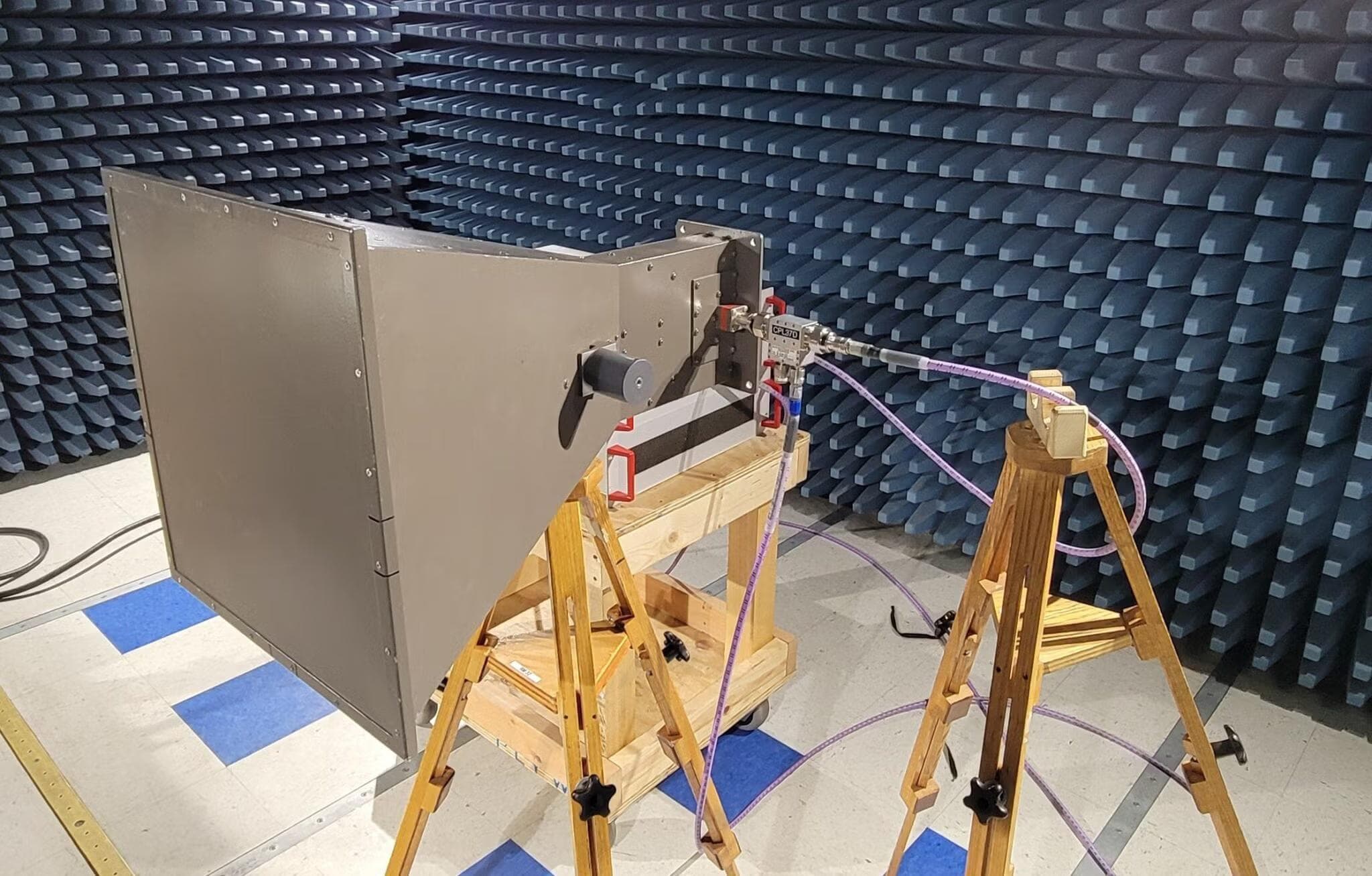
Shielded Enclosure (Test Chamber)
Most MIL-STD-461 testing is performed inside a shielded enclosure, often referred to as a Faraday cage. This is a large metallic room that provides electrical isolation between the outside environment and the test area. The enclosure must have continuous conductive surfaces with minimal gaps at seams, joints, and cable penetrations to prevent external ambient signals from contaminating measurements.
RF absorber material (typically ferrite tiles or foam absorbers) is required on the walls and ceiling to reduce reflected electromagnetic energy within the chamber. This improves measurement accuracy and repeatability by reducing standing waves and reflections. The absorber layout and performance requirements are specified in the standard.
Ground Plane
The EUT is placed on a metallic ground plane, typically a copper or aluminum sheet, which simulates the conductive surface of the installation platform (such as a ship deck or aircraft structure). The ground plane must be electrically bonded to the shielded enclosure floor or wall, with a bond resistance not exceeding 2.5 milliohms. Bonding straps must maintain a five-to-one length-to-width ratio or less.
For tabletop equipment, the ground plane sits on a non-conductive table at a specified height. For floor-standing equipment, the ground plane is on the floor. Composite (non-metallic) ground planes can be used when the actual installation uses composite structures.
Line Impedance Stabilization Network (LISN)
The LISN is a critical piece of test equipment used to control the impedance of the power supply connection and to provide a standardized measurement point for conducted emissions tests. The standard LISN uses a 50 μH inductor in series with each power lead and presents a known impedance to the EUT.
LISNs must be electrically bonded to the ground plane with a bond resistance not exceeding 2.5 milliohms. A 5 μH LISN may be used in specific cases, such as for 400 Hz aircraft power with short distribution paths, but this requires adjusting the conducted emission limits accordingly.
Cable Routing
MIL-STD-461 specifies precisely how cables must be routed during testing. Power cables are routed along the front edge of the bench for two meters, with a total length not exceeding 2.5 meters between the EUT connector and the LISN. Interconnecting cables must replicate the actual installation, including shielding, shield termination methods, and twisted pairs as specified for the real installation.
For interconnecting cables longer than 10 meters in the actual installation, at least 10 meters must be provided in the test setup. The first two meters are routed along the front of the test setup boundary, then the cable zigzags to the back of the setup. All cables are supported 5 centimeters above the ground plane.
EUT Bonding and Grounding
The bonding and grounding configuration during testing must replicate the actual installation. If the equipment uses a ground strap in the field, the same ground strap (with the same material, length, and width) must be used during testing. MIL-STD-461G added a requirement to measure and document the bonding impedance in the test report.
Applicability: Which Tests Apply to Your Equipment?
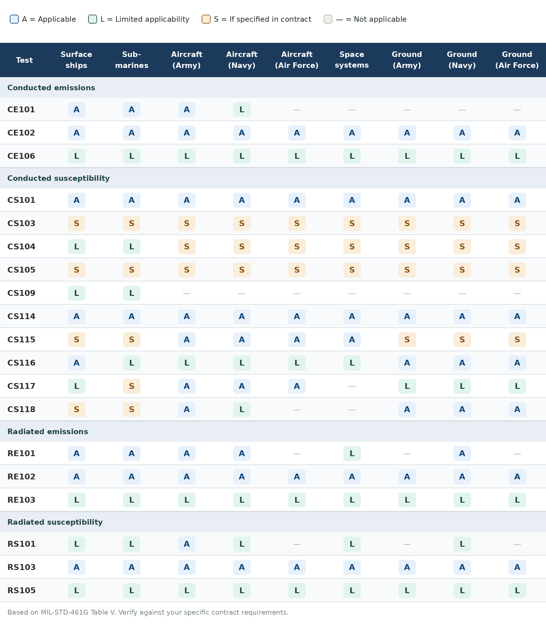
Not every test in MIL-STD-461 applies to every piece of equipment. The standard provides an applicability matrix (Table V in MIL-STD-461G) that maps each test method to specific platform types and installation environments. Tests are designated as:
- A — Applicable
- L — Limited applicability (with specific conditions)
- S — Applicable only when specified in the procurement contract
The platforms covered include surface ships, submarines, aircraft (Army, Navy, and Air Force), space systems and launch vehicles, and ground installations (Army, Navy, Air Force, and other DoD). The specific tests and limits also depend on the installation location — for example, whether the equipment is installed above deck or below deck on a ship, or whether it is internal or external to the aircraft structure.
Tailoring is a critical step. The procuring activity may adjust requirements to be more or less severe based on the actual electromagnetic environment the equipment will encounter. This tailoring should be performed by personnel knowledgeable about EMC issues affecting platform integration and should be documented in the EMI Test Procedure (EMITP).
Key Test Equipment for MIL-STD-461
Performing MIL-STD-461 testing requires specialized instrumentation. The primary equipment includes:
EMI Receiver or Spectrum Analyzer — Used to measure emission levels. Must comply with CISPR 16-1-1 requirements. Modern FFT-based receivers can significantly reduce scan times compared to traditional superheterodyne receivers.
Line Impedance Stabilization Networks (LISNs) — Provide controlled impedance for conducted emissions measurements. Both 50 μH and 5 μH configurations are used.
Current Probes — Used for CE101 current measurements and CS114/CS115/CS116 bulk cable injection calibration and monitoring.
Antennas — Multiple antenna types are needed to cover the full frequency range: rod antennas (below 30 MHz), biconical antennas (30 MHz to 200 MHz), double-ridge horn antennas (200 MHz to 18 GHz), and log-periodic antennas for various ranges.
Signal Generators and Power Amplifiers — Required for susceptibility testing to generate the prescribed test signals at sufficient power levels.
Field Probes and Sensors — Used to monitor and calibrate electric and magnetic field levels during RS101 and RS103 testing.
Bulk Current Injection Probes — Used for CS114, CS115, and CS116 to inject signals onto cable bundles.
Damped Sinusoidal Transient Generators — Purpose-built generators for CS116 testing that produce the required waveforms.
ESD Simulators — Required for CS118 (personnel-borne ESD) testing.
Frequently Asked Questions
How long does MIL-STD-461 testing take? A typical test program runs one to four weeks depending on the number of applicable tests, the complexity of the EUT, and the number of operating modes that must be evaluated. Programs that encounter failures and require troubleshooting may take longer.
How much does MIL-STD-461 testing cost? Costs vary significantly based on the scope of testing, lab location, and program complexity. A straightforward test program for a small electronic unit may cost tens of thousands of dollars, while a complex multi-mode system with extensive susceptibility requirements could cost significantly more. Pre-compliance testing can reduce formal lab costs by catching issues early.
Can I perform MIL-STD-461 testing in-house? Pre-compliance testing can be done in-house with appropriate equipment. However, formal qualification testing typically requires an accredited test laboratory (ISO/IEC 17025 or A2LA accredited) to produce certification documentation accepted by the procuring activity.
What happens if my equipment fails? Failure during qualification testing is common, especially in early development stages. The typical approach is to diagnose the failure mode, modify the design (improved shielding, cable routing, filtering), and retest. Many test labs offer engineering support for troubleshooting. This iterative process ultimately produces a more robust product.
Is MIL-STD-461 the same as commercial EMC standards? No. MIL-STD-461 is generally more stringent than commercial EMC standards like FCC Part 15, CISPR 32, or EN 55032. The test setup requirements, frequency ranges, and limit levels differ substantially. Equipment that passes commercial EMC testing may not pass MIL-STD-461, and vice versa.